

NCERT Solutions For Class 10 Science Chapter 13 Magnetic Effects of Electric Current
LearnFatafat offers free NCERT Solutions for Class 10 Science Chapter 13 Magnetic Effects of Electric Current. Chapter covers the topics like magnetic field due to current carrying straight conductor, magnetic field due to current through a circular loop, force on a current carrying conductor by a magnetic field, electric motor, electric generator and more. Check video lessons, notes and MCQ quizzes for Class 10 Science Chapter 13 Magnetic Effects of Electric Current click here to buy.
NCERT Solutions for Class 10 Science Chapter 13 Magnetic Effects of Electric Current
1. Which of the following correctly describes the magnetic field near a long straight wire?
(a) The field consists of straight lines perpendicular to the wire.
(b) The field consists of straight lines parallel to the wire.
(c) The field consists of radial lines originating from the wire.
(d) The field consists of concentric circles centred on the wire.
Answer: d) The field consists of concentric circles centred on the wire.
2. The phenomenon of electromagnetic induction is (a) the process of charging a body. (b) the process of generating magnetic field due to a current passing through a coil. (c) producing induced current in a coil due to relative motion between a magnet and the coil. (d) the process of rotating a coil of an electric motor.
Answer: (c) producing induced current in a coil due to relative motion between a magnet and the coil.
3. The device used for producing electric current is called a
(a) generator. (b) galvanometer. (c) ammeter. (d) motor.
Answer: (a) generator.
4. The essential difference between an AC generator and a DC generator is that
(a) AC generator has an electromagnet while a DC generator has permanent magnet.
(b) DC generator will generate a higher voltage.
(c) AC generator will generate a higher voltage.
(d) AC generator has slip rings while the DC generator has a commutator.
Answer: (d) AC generator has slip rings while the DC generator has a commutator.
5. At the time of short circuit, the current in the circuit
(a) reduces substantially. (b) does not change. (c) increases heavily. (d) vary continuously.
Answer: (c) increases heavily.
6. State whether the following statements are true or false.
(a) An electric motor converts mechanical energy into electrical energy.
Answer: False. [ In electrical motor, electrical energy is converted into mechanical energy. ]
(b) An electric generator works on the principle of electromagnetic induction.
Answer: True.
(c) The field at the centre of a long circular coil carrying current will be parallel straight lines.
Answer: True
(d) A wire with a green insulation is usually the live wire of an electric supply.
Answer: False. [ Wire with red insulation is live wire. Green insulation wire is wire for earthing in domestic circuits. ]
7. List three sources of magnetic fields.
Answer: Following are the sources of magnetic fields –
- Electromagnets
- Permanent magnets
- Current carrying conductor
8. How does a solenoid behave like a magnet? Can you determine the north and south poles of a current-carrying solenoid with the help of a bar magnet? Explain.
Answer: Long coil of circular loops made of insulated copper wire is called solenoid. When current flows through solenoid, magnetic field lines are produced around the solenoid. The magnetic field produced is similar to magnetic field produced by bar magnet. Following diagram shows magnetic field through a solenoid.
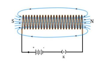
Considering the diagram, when north pole of bar magnet is brought near negative terminal of battery, magnet is repelled by solenoid. As it is known that like poles repel each other therefore, negative terminal of battery acts as north pole and other end acts as south pole.
9. When is the force experienced by a current–carrying conductor placed in a magnetic field largest?
Answer: When direction of current is perpendicular to direction of magnetic field, then the force experienced by current carrying conductor in a magnetic field is largest.
10. Imagine that you are sitting in a chamber with your back to one wall. An electron beam, moving horizontally from back wall towards the front wall, is deflected by a strong magnetic field to your right side. What is the direction of magnetic field?
Answer: Consider Fleming’s left hand rule. Therefore, magnetic field will be perpendicular to to direction of current and direction of force in a chamber. Here direction of current is from front of the wall to the back of the wall. This because electrons flow from the back of the wall to the front of the wall. Magnetic force is in rightward direction. Thus using fleming’s left hand rule, direction of magnetic field is in downward direction within the chamber.
11. Draw a labelled diagram of an electric motor. Explain its principle and working. What is the function of a split ring in an electric motor?
Answer:
Diagram : Click here to watch full video
Principal of Electric Motor:
Current carrying conductor if placed in magnetic field experiences a magnetic force that causes its motion.
Basic construction of Electric motor:
- Electric Motor consists of rectangular loop ABCD made of insulated copper wire.This loop is placed in two poles of magnet such that AB and CD are perpendicular to magnetic field.
- Ends of the loop are connected to two separate halves P and Q of split ring. P and Q are mounted on axle through insulation.
- The outer part of P and Q are connected to non-moving brushes X and Y. These brushes are connected to power source.
Working of electric motor:
- When the current starts flowing through the circuit it passes through the loop ABCD.
- Direction of current in branch AB is opposite to that of direction of current through CD.
- Since AB and CD are current carrying conductors placed in magnetic field thus they experience magnetic force.
- Force on AB causes it to move downwards while force acting on CD causes it to move upwards. This causes rotation of the loop and simultaneously rotation of Split rings P and Q
- At half of the rotation the split ring Q get connected with brush X and split ring P get connected with brush Y.
- It means that the direction of current in branches AB and CD is reversed and hence force acting on them is also reversed therefore branch CD moves downward and branch AB moves upwards.
- In this way the loop undergo continuous rotation.
12. Name some devices in which electric motors are used.
Answer: Following are some devices where electric motor is used –
- Electric fans
- Electric grinders
- Water pumps
13. A coil of insulated copper wire is connected to a galvanometer. What will happen if a bar magnet is (i) pushed into the coil, (ii) withdrawn from inside the coil, (iii) held stationary inside the coil?
Answer: If bar magnet is moved over solenoid then current induces in it, this is known as magnetic induction.
(i) Bar magnet when pushed in the insulated coil of copper wire, for a while electric current is induced in the coil and galvanometer needle shows deflection in a particular direction for that instant.
(ii) Bar magnet when withdrawn from inside the coil, current is induced in the coil for a while where the direction of the current is opposite. Therefore, galvanometer needle is deflected in opposite direction.
(iii) Magnet when held stationary inside the coil, then no current is induced and galvanometer does not show deflection.
14. Two circular coils A and B are placed closed to each other. If the current in the coil A is changed, will some current be induced in the coil B? Give reason.
Answer: When current in A coil is changed then magnetic field around it also changes. As B coil is placed close to A coil then change in magnetic field around A causes change in magnetic field B. This induces current in B coil. This due to electromagnetic induction.
15. State the rule to determine the direction of a
(i) magnetic field produced around a straight conductor-carrying current
Answer: Maxwell’s right hand thumb rule
(ii) force experienced by a current-carrying straight conductor placed in a magnetic field which is perpendicular to it
Answer: Fleming’s left hand rule
(iii) current induced in a coil due to its rotation in a magnetic field.
Answer: Fleming’s right hand rule
16. Explain the underlying principle and working of an electric generator by drawing a labelled diagram. What is the function of brushes?
Answer:
Principle :
Electric generator works on the principle of electromagnetic Induction. i.e. If conductor is moved in a magnetic field then current get induced in it.
Electric generator is a device that uses this principle to generate current. It uses mechanical energy to rotate conductor inside magnetic field to produce electricity. e.g. in hydroelectric power plant electricity is generated by using turbines. and motion of water.
Construction :
Diagram : Click here to watch full video
Basically It consists of rectangular coil ABCD placed between magnetic field of permanent magnet. Two ends of coil are connected to Ring R1 and Ring R2 and these are attached to axle through insulation. These rings are connected to brushes B1 and B2 respectively. galvanometer is connected to these brushes for measuring current.
Working:
Generation of Alternating Current
- Mechanical energy is used to rotate axle thereby rotating the rings. This causes arm AB to move up and arm CD to move down.
- Since this loop is present in magnetic field hence current is get induced in it. current flows in the direction ABCD. At half of the rotation CD starts moving up and AB starts moving down thus direction of current through the loop reverses i.e. current flows in direction DCBA.
- Current value is indicated by galvanometer. For single loop current is very small. As the number of turns increases total current will be sum of individual currents of all turns hence large current will be produced.
- In full rotation direction of current changes after equal intervals of time hence such current is called alternating current. and the device used to generate alternating current is called AC Generator.
Generation of Direct current
Diagram : Click here to watch full video
- In order to produce direct current split-ring is used.
- With this arrangement one brush is always connected to branch that goes up and other is connected to branch that always goes down.
- This causes production of current in single direction i.e. direct current or DC.Such type of current generator is called DC generator.
17. When does an electric short circuit occur?
Answer: When resistance in a circuit becomes low, current flowing through it becomes high. This causes short circuits. It occurs when large number of appliances single socket or high power appliances are connected to light circuits. If insulation of live and neutral wire is damaged then, they touch each other, which increases current flowing in the circuit, causing short circuits.
18. What is the function of an earth wire? Why is it necessary to earth metallic appliances?
Answer: Function of an electric wire is to prevent user from shock. When earth wire is connected to metal appliances, it connects the appliances to the earth. In case of current leakage, earth wire transfers current to earth, thereby preventing from getting shock to the user.
Check other lessons NCERT Solutions for Class 10
Download free NCERT textbook class 10 Science – Chapter 13 Magnetic Effects of Electric Current
CBSE Class 10
Access Class 10 video lessons online (internet required) or offline(internet not required) in SD Card, Pendrive, DVD, Tablet.
Chapter 13 -Magnetic Effects of Electric Current


